
CNC machining is widely used in precision manufacturing because it delivers high dimensional accuracy, repeatability, and consistent component quality. However, even with advanced CNC equipment, machining defects can occur due to incorrect cutting parameters, tool wear, machine vibration, improper workholding, material properties, or insufficient process control.
These problems can affect component dimensions, surface quality, mechanical performance, and assembly compatibility. For manufacturers producing precision aluminum parts, stainless steel components, and other custom-machined products, identifying defects early is essential to maintaining production efficiency and reducing manufacturing costs.
Understanding common CNC machining defects helps engineers and manufacturers identify the root causes of quality problems and implement effective corrective actions.
This guide explores the most frequent CNC machining defects, including chatter marks, dimensional inaccuracies, burrs, surface scratches, tool marks, and thermal deformation. It also explains practical troubleshooting methods and preventive measures to improve machining quality.
1. What Are Common CNC Machining Defects?
CNC machining defects are unwanted variations or imperfections that occur during milling, turning, drilling, tapping, or other machining operations.
They may affect the appearance, dimensions, geometry, or functional performance of a finished component.
Some defects are primarily cosmetic, while others can cause serious assembly problems or compromise component reliability.
Common CNC machining defects include:
- Chatter marks and vibration patterns.
- Dimensional errors and out-of-tolerance features.
- Surface scratches and visible tool marks.
- Burrs and sharp edges.
- Poor surface roughness.
- Tool wear and uneven cutting surfaces.
- Thermal deformation and warping.
- Incorrect hole positions and thread defects.
- Material tearing and built-up edge.
The severity of these defects depends on machining conditions, material characteristics, machine capability, tooling quality, and inspection procedures.
Identifying the defect type is the first step toward determining the correct solution.
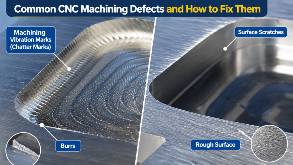
2. Chatter Marks and Machining Vibration Marks
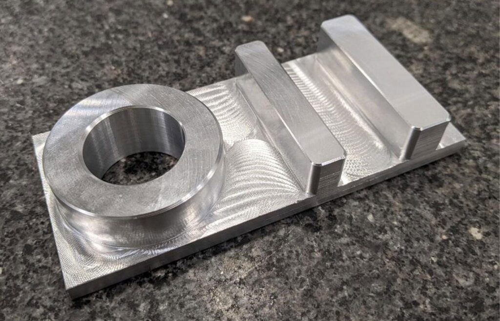
Chatter marks are among the most recognizable surface defects in CNC machining. They typically appear as repetitive waves, lines, or irregular patterns on a machined surface.
These marks are caused by vibrations between the cutting tool, workpiece, spindle, and machine structure during material removal.
Machining vibration marks can reduce surface quality, affect dimensional accuracy, accelerate tool wear, and create inconsistent results across production batches.
Common Causes of Chatter Marks
1. Incorrect Cutting Parameters
Excessive spindle speed, inappropriate feed rates, or overly aggressive cutting depths can create unstable cutting conditions.
2. Insufficient Workpiece Clamping
If the workpiece is not securely fixed, cutting forces may cause it to move or vibrate during machining.
3. Excessive Tool Overhang
A long tool extension reduces tool rigidity and increases the risk of vibration, particularly during deep-pocket machining.
4. Worn or Damaged Cutting Tools
Blunt cutting edges and damaged tool geometry can generate uneven cutting forces and contribute to chatter.
5. Poor Machine Rigidity
Loose machine components, worn spindle bearings, or inadequate fixture rigidity can increase vibration during machining.
How to Fix Chatter Marks
- Adjust spindle speed and feed rate to achieve stable cutting conditions.
- Reduce axial or radial depth of cut when necessary.
- Use shorter, more rigid cutting tools.
- Improve workpiece clamping and fixture support.
- Replace worn or damaged cutting tools.
- Check spindle condition, toolholder balance, and machine rigidity.
- Use suitable toolpaths and cutting strategies to reduce cutting-force fluctuations.
For deep cavities and thin-wall components, manufacturers should pay particular attention to tool overhang, workpiece support, and machining sequence.
Prevention tip: Monitor machining vibration during production and establish stable cutting parameters for each material, tool diameter, and machining operation.
3. Dimensional Errors in CNC Machined Parts
Dimensional accuracy is one of the most important quality requirements in precision CNC manufacturing.
A component may have an excellent surface appearance but still fail inspection if its hole diameters, slot widths, thicknesses, or geometric tolerances do not meet the engineering drawing.
Dimensional error CNC parts can create assembly problems, excessive clearances, interference fits, and product performance issues.
Common Causes of Dimensional Errors
1. Incorrect Tool Offset Settings
Incorrect tool length or radius compensation can cause machining dimensions to deviate from the programmed values.
2. Tool Wear
As cutting tools wear, their effective cutting geometry changes, potentially producing dimensional variations.
3. Thermal Expansion
Heat generated during machining can cause the machine, cutting tool, or workpiece to expand. Temperature changes during and after machining may affect final measurements.
4. Workpiece Movement
Insufficient clamping force or poor fixture positioning can cause the workpiece to shift during cutting.
5. Material Residual Stress
Removing material from a stressed workpiece can cause internal stress redistribution and dimensional distortion.
6. Incorrect CNC Programming
Errors in coordinate systems, cutter compensation, work offsets, or machining sequences can produce incorrect dimensions.
How to Fix Dimensional Errors
- Verify tool offsets and work coordinate systems before machining.
- Inspect cutting tools and replace worn inserts or end mills.
- Use appropriate cutting parameters to reduce excessive heat generation.
- Improve workholding and fixture stability.
- Allow components to reach a stable temperature before final inspection.
- Use rough machining followed by finishing passes.
- Consider stress-relieved material conditions for distortion-sensitive parts.
- Inspect critical dimensions using calibrated measuring equipment.
For precision components, manufacturers should establish inspection checkpoints during machining rather than relying exclusively on final inspection.
Recommended Inspection Equipment
| Inspection Equipment | Primary Application |
|---|---|
| Digital calipers | General dimensional measurements |
| Micrometers | Precise thickness and diameter measurements |
| Height gauges | Vertical dimensions and feature positions |
| Bore gauges | Internal diameter measurements |
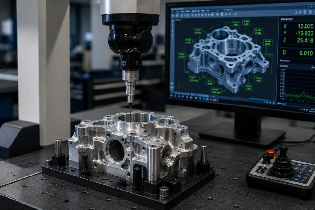
| Coordinate Measuring Machines (CMM) | Complex geometry and positional accuracy |
| Surface roughness testers | Surface texture evaluation |
| Thread gauges | Thread size and fit verification |
For components with demanding geometric tolerances, CMM inspection can help identify deviations in position, flatness, parallelism, concentricity, and other specified characteristics.
4. Surface Finish Defects in CNC Machining
Surface finish is a critical quality characteristic for many CNC-machined components.
Poor surface quality can affect appearance, sealing performance, friction, fatigue behavior, and assembly compatibility.
Surface finish defects CNC manufacturing teams commonly encounter include rough surfaces, scratches, uneven tool marks, and inconsistent finishing patterns.
Common Causes of Surface Finish Defects
1. Incorrect Feed Rate
Excessive feed rates can create visible tool marks and increase surface roughness.
2. Improper Tool Geometry
An unsuitable tool nose radius, cutting edge, or flute design may produce poor surface quality.
3. Tool Wear
Worn cutting edges can generate rough surfaces, tearing, and inconsistent machining patterns.
4. Material Characteristics
Some materials, particularly soft or ductile metals, may develop built-up edges or material smearing under unsuitable cutting conditions.
5. Insufficient Coolant or Lubrication
Poor lubrication can increase friction, heat generation, and material adhesion to the cutting tool.
6. Incorrect Finishing Strategy
Using an inappropriate finishing allowance or machining direction can result in uneven surfaces.
How to Fix Surface Finish Defects
- Optimize feed rate and spindle speed.
- Use sharp cutting tools with suitable geometry.
- Select appropriate finishing tools for the material.
- Apply suitable coolant or lubrication.
- Use consistent finishing passes.
- Improve toolpath direction and cutting engagement.
- Remove built-up material from cutting edges.
- Verify surface roughness against the engineering specification.
Common Surface Finishing Methods
Some CNC components require additional finishing operations after machining.
| Finishing Method | Main Purpose | Typical Applications |
|---|---|---|
| Deburring | Remove sharp edges and burrs | Precision mechanical parts |
| Sanding | Improve surface smoothness | General machined components |
| Polishing | Produce a smoother or reflective surface | Decorative metal parts |
| Bead blasting | Create a uniform matte appearance | Aluminum housings |
| Anodizing | Improve aluminum surface protection | Aluminum CNC parts |
| Powder coating | Add a protective decorative coating | Enclosures and exterior components |
The finishing process should be selected according to the part’s material, functional requirements, appearance expectations, and dimensional tolerances.
5. Burr Formation and Sharp Edges
Burrs are unwanted raised edges or small pieces of material that remain attached to a component after machining.
They commonly occur around drilled holes, milled slots, intersecting features, and machined edges.
Although small burrs may appear insignificant, they can interfere with assembly, damage seals, affect component safety, and create inspection problems.
Common Causes of Burr Formation
- Blunt or worn cutting tools.
- Incorrect feed rates and cutting speeds.
- Unsuitable tool geometry.
- Poor machining direction.
- Material ductility.
- Inadequate cutting support during breakthrough operations.
How to Reduce Burr Formation
1. Use Sharp Cutting Tools
Sharp cutting edges help produce cleaner material removal and reduce unwanted deformation.
2. Optimize Feed and Speed
Appropriate cutting parameters help control material deformation during machining.
3. Use Suitable Toolpaths
Adjusting tool entry and exit strategies can reduce burr formation, especially around holes and thin edges.
4. Apply Appropriate Deburring Operations
Depending on part geometry, manufacturers may use manual deburring, mechanical brushing, abrasive finishing, or specialized deburring tools.
5. Specify Edge Requirements
Engineering drawings should clearly identify required chamfers, radii, and edge conditions.
For precision CNC parts, deburring should be treated as a controlled manufacturing operation rather than an informal final step.
6. Tool Wear and Poor Cutting Performance
Cutting tools gradually deteriorate during machining because of mechanical loading, friction, heat, and material interaction.
Excessive tool wear can cause dimensional inaccuracies, poor surface finish, increased machining forces, and unexpected production interruptions.
Common Types of Tool Wear
- Flank Wear: Material gradually wears away from the clearance face of the cutting tool.
- Crater Wear: A depression develops on the tool’s rake face due to chip interaction and heat.
- Chipping: Small pieces of the cutting edge break away during machining.
- Built-Up Edge: Workpiece material adheres to the cutting edge, changing the effective tool geometry.
- Thermal Damage: Excessive cutting temperatures can degrade tool performance.
How to Reduce Tool Wear
- Select cutting tools suitable for the workpiece material.
- Optimize cutting speed, feed rate, and depth of cut.
- Use appropriate coatings and carbide grades.
- Apply suitable coolant or lubrication where required.
- Maintain proper tool alignment and workholding.
- Establish tool inspection and replacement intervals.
- Monitor spindle load and machining performance.
For aluminum machining, sharp tools with suitable polished cutting edges and effective chip evacuation can help reduce material adhesion and improve surface quality.
For stainless steel and other difficult-to-machine materials, manufacturers should carefully manage cutting temperature, tool wear, and cutting forces.
7. Thermal Deformation and Warping
Thermal deformation occurs when heat generated during machining causes the workpiece or machine components to expand unevenly.
After machining, temperature changes and residual stress redistribution can cause the component to change shape.
This problem is particularly important when machining thin-wall components, large aluminum plates, precision housings, and components with demanding flatness requirements.
Common Causes of Thermal Deformation
- Excessive cutting temperatures.
- High material removal rates.
- Insufficient or unsuitable coolant application.
- Uneven material removal.
- Residual stresses in raw material.
- Inadequate workholding strategies.
- Thin-wall geometries with insufficient rigidity.
How to Prevent Thermal Deformation
1. Use Balanced Machining Sequences
Remove material in a controlled and balanced manner to reduce uneven stress redistribution.
2. Control Cutting Temperature
Optimize cutting parameters and use suitable coolant or lubrication.
3. Use Appropriate Workholding
Avoid excessive clamping pressure that can distort thin or flexible components.
4. Select Suitable Raw Material Conditions
Stress-relieved material may help improve dimensional stability for distortion-sensitive applications.
5. Use Roughing and Finishing Separately
Rough machining removes most of the material, while finishing operations restore the required geometry after initial stress redistribution.
6. Inspect After Temperature Stabilization
Allow parts to reach a stable temperature before performing final dimensional measurements.
For demanding components, manufacturers may also consider intermediate stress-relief operations where appropriate for the material and specification.
8. Hole Position Errors and Thread Defects
Holes and threaded features are important functional elements in many CNC-machined components.
Incorrect hole positions, inconsistent diameters, damaged threads, and poor thread engagement can cause assembly failures.
Common Causes of Hole Position Errors
- Incorrect coordinate programming.
- Improper workpiece positioning.
- Tool runout.
- Drill deflection.
- Incorrect tool selection.
- Insufficient machine rigidity.
- Incorrect datum or work offset settings.
Common Causes of Thread Defects
- Incorrect tap selection.
- Incorrect pre-drilled hole diameter.
- Poor alignment between the tap and hole.
- Inappropriate tapping speed.
- Inadequate lubrication.
- Tool wear or chip accumulation.
- Incorrect thread depth.
How to Fix Hole and Thread Defects
- Verify drawing dimensions and coordinate positions.
- Use suitable drilling and tapping tools.
- Check tool runout and alignment.
- Confirm the correct tap drill diameter.
- Use appropriate cutting fluids for the material.
- Ensure chips can evacuate from the hole.
- Inspect finished threads using calibrated thread gauges.
- Verify critical hole positions through CMM inspection when necessary.
For deep holes and blind threaded features, proper chip evacuation and tapping strategy are especially important.
9. Material Tearing and Built-Up Edge
Material tearing occurs when the cutting tool pulls or deforms workpiece material rather than producing a clean cutting action.
It can create irregular surface textures, rough edges, and inconsistent dimensions.
Built-up edge is a related problem in which workpiece material adheres to the cutting tool during machining.
These problems are particularly common when machining certain ductile materials under unsuitable cutting conditions.
Common Causes
- Insufficient cutting speed.
- Excessive friction between tool and workpiece.
- Blunt cutting edges.
- Incorrect tool geometry.
- Inadequate lubrication.
- Poor chip evacuation.
- Unsuitable cutting parameters for the material.
How to Fix Material Tearing
- Use sharp tools with appropriate cutting geometry.
- Optimize cutting speed and feed rate.
- Apply suitable coolant or lubrication.
- Select tools designed for the specific material.
- Improve chip evacuation.
- Avoid excessive rubbing or repeated cutting passes.
- Inspect cutting edges regularly.
For aluminum alloys, selecting suitable aluminum-specific cutting tools can help reduce built-up edge and improve the quality of machined surfaces.
10. CNC Machining Defects: Root Causes and Solutions at a Glance
The following table summarizes common CNC machining defects and their recommended corrective actions.
| CNC Machining Defect | Main Cause | Recommended Solution |
|---|---|---|
| Chatter marks | Machine or tool vibration | Adjust cutting parameters and improve rigidity |
| Dimensional errors | Incorrect offsets or tool wear | Verify offsets and inspect tools |
| Poor surface finish | Incorrect feed or worn tools | Optimize finishing parameters |
| Burr formation | Cutting deformation | Use sharp tools and deburring operations |
| Tool wear | Heat and cutting forces | Optimize tooling and machining conditions |
| Thermal deformation | Excessive heat and residual stress | Use balanced machining and temperature control |
| Hole position errors | Incorrect coordinates or tool deflection | Verify datums and tool alignment |
| Thread defects | Incorrect tapping conditions | Check drill size and tapping parameters |
| Material tearing | Built-up edge and poor cutting conditions | Improve tool geometry and lubrication |
This troubleshooting reference can help production engineers identify likely causes and prioritize corrective actions.
11. How to Prevent CNC Machining Defects Before Production
Correcting defects after they occur is important, but preventing them during process planning is generally more efficient.
A systematic quality management approach can help manufacturers reduce scrap, improve repeatability, and maintain consistent component quality.
11.1 Review Engineering Drawings
Before machining begins, engineers should review the drawing and identify critical dimensions, geometric tolerances, surface roughness requirements, and material specifications.
Potential manufacturing problems should be identified through Design for Manufacturability (DFM) review.
11.2 Select Appropriate Materials
Different materials have different machinability characteristics.
For example:
- Aluminum 6061 offers good machinability and corrosion resistance.
- Aluminum 7075 provides higher strength but requires careful consideration of application and corrosion protection.
- Stainless steel 304 offers good corrosion resistance but can be more challenging to machine.
- POM provides good dimensional stability and machinability for many plastic components.
Selecting the right material can help reduce cutting difficulties and improve finished-part performance.
11.3 Optimize Cutting Parameters
Machining parameters should be matched to the material, tool geometry, machine capability, and part geometry.
Important parameters include:
- Spindle speed.
- Feed rate.
- Depth of cut.
- Radial engagement.
- Toolpath strategy.
- Coolant application.
Production parameters should be validated rather than copied blindly between different machines or materials.
11.4 Maintain CNC Machines Regularly
Machine maintenance directly affects manufacturing accuracy and reliability.
Regular checks should include:
- Spindle condition.
- Axis positioning accuracy.
- Machine alignment.
- Toolholder condition.
- Lubrication systems.
- Coolant systems.
- Fixture and clamping condition.
Preventive maintenance helps reduce unexpected vibration, positioning errors, and machining inconsistencies.
11.5 Implement In-Process Inspection
Inspecting components during machining helps identify problems before an entire production batch is affected.
Recommended quality checkpoints include:
- Raw material verification.
- First-article inspection.
- In-process dimensional checks.
- Tool condition monitoring.
- Final dimensional inspection.
- Surface quality verification.
For critical components, manufacturers should define inspection methods and acceptance criteria before production starts.
11.6 Establish Clear Quality Standards
Consistent manufacturing requires clearly documented quality requirements.
Depending on the application, these may include:
- Dimensional tolerances.
- Geometric Dimensioning and Tolerancing (GD&T).
- Surface roughness specifications.
- Material certifications.
- Surface treatment requirements.
- Thread inspection requirements.
- Visual inspection criteria.
- Traceability and inspection records.
A well-defined quality control process helps ensure that every production batch meets the customer’s requirements.
12. Why Choosing a Quality-Controlled CNC Machining Supplier Matters
Even a well-designed component can experience manufacturing problems if machining processes are not properly controlled.
Working with an experienced CNC machining supplier helps reduce the risk of defects and improve consistency throughout production.
When evaluating a supplier, consider the following capabilities.
Equipment and Manufacturing Capabilities
A capable supplier should have suitable CNC milling, turning, and multi-axis machining equipment for the required part geometry.
Machine condition, workholding capability, and process stability are important factors in maintaining dimensional accuracy.
Engineering and DFM Support
Professional engineering support can identify potential issues involving:
- Thin-wall structures.
- Deep cavities.
- Small holes and internal threads.
- Tight dimensional tolerances.
- Tool accessibility.
- Material selection.
- Surface finishing.
Early design feedback can help prevent manufacturing problems before production begins.
Inspection and Quality Control
A reliable manufacturer should have appropriate measurement equipment and documented inspection procedures.
Depending on the component requirements, these may include CMM systems, micrometers, height gauges, thread gauges, and surface roughness testers.
Surface Finishing Capabilities
Machining quality does not end when the cutting operation is complete.
Many components require additional processes such as anodizing, bead blasting, polishing, powder coating, or deburring.
These operations should be coordinated with dimensional requirements to prevent finishing-related defects.
13. Conclusion: How to Achieve Defect-Free CNC Machining
Common CNC machining defects can result from multiple factors, including incorrect cutting parameters, tool wear, machine vibration, material properties, thermal deformation, and inadequate quality control.
Chatter marks can often be reduced through improved machine rigidity and optimized cutting conditions. Dimensional errors require accurate tool offsets, stable workholding, and effective inspection. Surface finish problems can be addressed through appropriate tooling, feed rates, lubrication, and finishing methods.
However, achieving consistent machining quality requires more than correcting individual defects. It requires a systematic manufacturing approach that combines engineering review, suitable material selection, process optimization, machine maintenance, and inspection throughout production.
For businesses manufacturing precision components, working with an experienced supplier can help reduce defects, improve dimensional consistency, and minimize unnecessary production costs.
From material selection and machining strategy to dimensional inspection and surface finishing, professional quality-controlled custom CNC machining helps ensure that finished components meet demanding engineering and quality requirements.
Frequently Asked Questions (FAQs)
1. What causes chatter marks on CNC machined surfaces?
Chatter marks are mainly caused by vibration between the cutting tool, workpiece, spindle, and machine structure during machining. Common contributing factors include excessive tool overhang, incorrect cutting parameters, insufficient workpiece clamping, worn cutting tools, and inadequate machine rigidity.
To reduce chatter marks, manufacturers should optimize spindle speed and feed rate, reduce cutting depth when necessary, improve workpiece support, use shorter and more rigid tools, and inspect machine and toolholder conditions.
2. Why do machined parts have inconsistent dimensions?
Inconsistent dimensions can result from tool wear, incorrect tool offsets, thermal expansion, workpiece movement, residual material stress, and machine positioning errors.
Manufacturers can improve dimensional consistency by verifying CNC programs and tool compensation, maintaining stable workholding, controlling machining temperatures, replacing worn tools, and implementing regular in-process inspection.
For precision components, calibrated measuring equipment and CMM inspection can help identify dimensional variations before parts reach final assembly.
3. How to reduce surface scratches during finishing?
Surface scratches can be reduced by maintaining clean work environments, using appropriate abrasives, selecting suitable finishing tools, and preventing finished components from contacting hard or contaminated surfaces.
Additional preventive measures include:
- Clean parts thoroughly before finishing.
- Use appropriate sanding or polishing materials.
- Avoid excessive finishing pressure.
- Separate finished components with protective materials.
- Use clean handling gloves when required.
- Protect finished surfaces during storage and transportation.
- Inspect components after each finishing operation.
For anodized or powder-coated CNC parts, proper handling and packaging are especially important because scratches can damage the finished protective layer.


