
Surface finish affects more than the appearance of a CNC-machined component. It influences sealing performance, friction, wear, coating consistency, and the fit between mating parts. Combined with GD&T (geometric dimensioning and tolerancing), specified CNC surface roughness Ra translates functional requirements into measurable manufacturing criteria. For mechanical engineers and sourcing teams, the core challenge is defining a proper finish that meets design intent without unnecessary polishing, extra inspection or added rework cost. We are a China-based CNC machining factory specializing in custom prototypes and low-volume precision parts for automation, medical, aerospace and e-bike projects. We help designers balance roughness, GD&T tolerances and secondary finishing in one drawing package.
Definition
Surface roughness describes the fine-scale irregularities left on a manufactured surface. The most commonly specified parameter is Ra, or arithmetic average roughness. It represents the average absolute deviation of the measured surface profile from its mean line over a defined sampling length. Ra is normally expressed in micrometres (µm). A lower Ra value indicates a smoother measured profile, but it does not capture the full surface characteristic. Two surfaces with identical Ra can differ greatly in peak shape, valley depth, lay direction and load-bearing performance. When tight assembly is required, roughness must be defined alongside GD&T controls such as flatness, perpendicularity, position and profile tolerance. GD&T controls the overall form and alignment of the feature, while Ra controls its micro-texture. Neither specification alone guarantees a functional mating surface. For this reason, engineering drawings should clearly mark the roughness parameter, target value, measurement method, GD&T callouts and the exact surfaces these requirements apply to.
How It Works
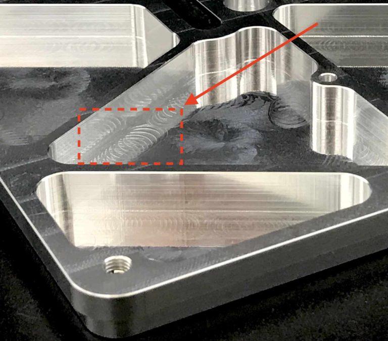
CNC surface roughness is driven by tool geometry, feed rate, spindle speed, material properties, machine rigidity, tool wear and vibration. During milling or turning, the cutting tool leaves a predictable profile defined partially by feed rate and tool nose radius. Built-up edge, chip re-cutting and material tearing will degrade surface quality. Secondary finishing operations alter both surface texture and sometimes GD&T compliance:
- Grinding: Abrasive material removal, delivers consistent fine roughness while maintaining strict form tolerances.
- Polishing: Flattens surface peaks and removes tool marks, but can remove small amounts of material and break GD&T edge / size tolerances.
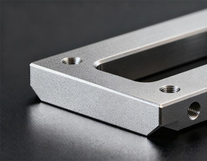
- Bead blasting: Creates uniform matte texture; roughness depends on media, pressure and blast distance. It does not correct flatness or position errors.
- Anodizing: Grows an aluminum oxide layer. It changes surface texture and adds material thickness, which may shift size and profile tolerances.
- Sealing: Closes pores on anodic coatings; it cannot fix poor underlying geometry or form errors defined in GD&T. All roughness and GD&T inspections should be performed after the final finishing sequence relevant to the part’s function.
Key Parameters
The table below shows typical Ra ranges paired with common GD&T considerations for reference only, not guaranteed capability:
表格
| Process or condition | Typical Ra range (µm) | Common use | GD&T Notes |
|---|---|---|---|
| CNC milling, general finish | 1.6–6.3 | Brackets, housings, non-critical faces | Loose form tolerances, no tight flatness requirement |
| CNC milling, fine finish | 0.8–1.6 | Mating faces, visible machined surfaces | Usually paired with flatness / parallelism callouts |
| CNC turning | 0.8–3.2 | Shafts, bores, cylindrical interfaces | Often combined with circularity or runout tolerance |
| Grinding | 0.2–0.8 | Precision fits, sealing functional surfaces | Can hold tight GD&T form tolerances consistently |
| Fine polishing | 0.05–0.4 | Optical, sliding or cosmetic surfaces | High risk: polishing may break sharp edges and size tolerances |
| Bead blasting | 1.6–6.3 | Matte cosmetic uniform texture | No improvement to flatness, position or profile tolerance |
Avoid assigning the same Ra value to every face of a component. A manifold may require 0.8–1.6 µm on O-ring sealing grooves (with flatness GD&T) while non-functional outer surfaces can use a rougher, cheaper finish. Separate specs reduce cost and simplify inspection.
Pros & Cons
When specified together with GD&T, controlled roughness improves part consistency and guides machinists to select proper cutting and finishing workflows. ✅ Benefits
- Predictable sealing, friction and wear behaviour on sliding or static interfaces
- Stable coating adhesion and uniform cosmetic results across batches
- Clear, inspectable acceptance criteria for both texture and geometry
- Eliminates unnecessary high-cost polishing for non-critical surfaces
❌ Drawbacks
- Finer Ra usually requires slower feeds, extra finishing passes or grinding, raising lead time and cost
- Polishing and blasting can shift dimensions and violate existing GD&T tolerances if allowance is not reserved
- Mirror-smooth surfaces are not always optimal; some gaskets and coatings perform better with a controlled moderate texture
Typical Applications
Surface roughness paired with GD&T is critical for parts that seal, slide, rotate or mate precisely: hydraulic manifolds, valve bodies, bearing housings, precision fixtures, medical hardware and automation locating jigs. In aerospace assemblies, roughness on fatigue-critical surfaces works alongside profile GD&T to control stress concentration. For anodized aluminum enclosures, cosmetic panels may be bead blasted before coating, while threaded holes, bearing seats and sealing lands must be masked to preserve their Ra and geometric tolerances.
Design & Machining Notes
Always define roughness based on function, not aesthetics. For static O-ring face seals, Ra 0.8–1.6 µm is a typical starting point, but final values must follow seal vendor specifications. When you add GD&T callouts and surface finish requirements on the same feature:
- State whether roughness and GD&T apply before or after anodizing / blasting / polishing
- Mark masking zones for sealing or precision fit surfaces
- Reserve material allowance for finishing if polishing or grinding is required
- Specify that GD&T inspection is completed after all secondary operations
- Separate tolerance zones for form, position and surface texture
Our team reviews your CAD drawings and GD&T stack-up before production for low-volume CNC machined parts, to avoid conflicts between surface finish requirements and geometric tolerances.
FAQ
What Ra value works for CNC sealing surfaces with flatness GD&T?
For most static elastomer face seals, Ra 0.8–1.6 µm is a practical baseline. The final requirement depends on seal material, pressure, fluid type and the seal supplier’s datasheet. When flatness or profile tolerance is tight, grinding is preferred over hand polishing to keep GD&T within range.
Will anodizing change my surface roughness and GD&T results?
Anodizing builds an oxide layer and adds thickness, so it alters surface texture and can shift dimensional and geometric results. Bead blasting pre-treatment will increase Ra. If roughness or GD&T is critical, inspect parts after coating or mask those features.
Can polishing break my GD&T tolerances?
Yes. Polishing removes material and rounds sharp edges. It can violate flatness, size, position and profile tolerances. If polishing is required, add machining allowance and define all GD&T and roughness acceptance rules after polishing.


