A CNC machined part can satisfy all individual dimensional tolerances yet still fail during assembly. The root cause is usually the positional relationship between features, not the size of a single hole, face or shaft. This is where Geometric Dimensioning and Tolerancing (GD&T) plays a key role.
GD&T for CNC machining helps engineers clearly define how part features relate to each other, so drawings are easier to machine, inspect and interpret. When applied correctly, GD&T guarantees functional accuracy without imposing overly tight tolerances on every feature.
Definition
Geometric Dimensioning and Tolerancing (GD&T) is a standardized engineering drawing notation system that defines allowable variation in form, orientation, location and runout of part features.
Unlike traditional coordinate tolerancing which only sets limits for individual dimensions, GD&T governs geometric relationships across features. It relies on standard symbols, feature control frames and datums to deliver accurate design intent.
For CNC machined components, GD&T is highly valuable when holes, slots, mounting faces, shafts and mating surfaces demand precise alignment during assembly. A GD&T tolerance specifies permitted deviation for a defined geometric characteristic. Its tolerance value and scope should be determined by the part’s functional needs and actual manufacturing capability.
How It Works
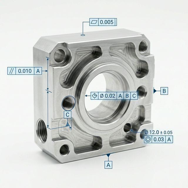
GD&T communicates engineering requirements via feature control frames attached to target features or dimensions on technical drawings.
A standard feature control frame states the geometric characteristic, tolerance value and referenced datums. Datums establish theoretical reference planes, axes or points for part measurement.
The typical workflow:
- Identify functional features: Pin down surfaces, holes and axes that control assembly performance.
- Select datums: Define practical reference features matching how the part is fixtured for assembly or inspection.
- Assign geometric controls: Apply position, flatness, perpendicularity and other controls based on functional goals.
- Set tolerance values: Define acceptable variation according to design requirements and machining capacity.
- Plan inspection: Select proper measuring tools and methods to validate each requirement.
Well-defined datum structures help machinists understand part positioning rules and enable inspectors to get consistent measurement results.
Key Parameters
Each GD&T symbol controls a unique geometric property. Selection depends on the feature’s function.
表格
| GD&T Symbol | What It Controls | Common CNC Application |
|---|---|---|
| Position | Location of features relative to datums | Hole patterns, mounting features |
| Flatness | Surface form (no datum required) | Mounting faces, sealing surfaces |
| Perpendicularity | 90° orientation against a datum | Holes relative to reference faces |
| Parallelism | Parallel orientation against a datum | Opposing faces, guide surfaces |
| Circularity | Roundness of a 2D cross-section | Precision shafts, cylindrical features |
| Cylindricity | Full 3D cylindrical form | Precision bores and shafts |
| Profile of a Surface | 3D contour shape | Complex milled curved surfaces |
| Total Runout | Deviation over a rotating surface | Rotating shafts, cylindrical mating parts |
Position is among the most widely used GD&T controls in CNC machining. It regulates the location accuracy of holes or other features relative to datums, and works far better than separate coordinate tolerances for hole patterns that must mate with matching components.
Flatness controls the inherent form of a surface independent of any datum. It is critical for stable contact surfaces but does not control how that surface angles toward other features.
Perpendicularity and parallelism manage orientation. They are widely used for mounting faces, locating surfaces and bores where angular accuracy directly affects assembly.
Pros & Cons
Correct GD&T implementation brings clear benefits:
- Clear design intent: Engineers communicate geometric relationships between features unambiguously.
- Reliable assembly: Position and orientation controls ensure parts fit as designed.
- Repeatable inspection: Datum frameworks create unified measurement standards.
- Greater manufacturing flexibility: Reasonable geometric tolerances avoid over-constraining non-critical features.
- Less misinterpretation: Standard symbols reduce confusion between design, machining and QC teams.
GD&T does require solid technical know-how, however. Poor datum selection or unnecessarily strict tolerance zones can raise machining difficulty and part cost. Complex GD&T calls for specialized inspection equipment and extra measuring time.
Typical Applications
GD&T is essential for CNC parts where feature relationships directly determine performance:
- Medical equipment: Instrument housings, precision bores and alignment-critical mounting interfaces.
- Aerospace: Structural brackets, precision housings with strict geometric requirements.
- Industrial automation: Fixture plates, actuator housings, sensor mounts and locating features.
- E-bike systems: Motor housings, bearing seats, shafts and mating mounting interfaces.
- Electronics: Connector bodies, heat sinks and enclosures with accurately positioned holes.
In these scenarios, geometric controls ensure parts pass assembly validation, instead of merely meeting isolated dimension checks.
Design & Machining Tips
Good GD&T starts with clear functional intent. Follow these guidelines to lower machining complexity and inspection cost:
- Set datums based on real assembly conditions: Choose reference surfaces matching how the part sits in final assembly.
- Use Position tolerances for critical hole patterns: Ideal when hole alignment with mating hardware matters.
- Avoid over-specifying tolerances: Reserve tight geometric tolerances only for features impacting fit and function.
- Separate size and geometric controls: A hole’s diameter tolerance does not automatically define its location or orientation. Specify both when needed.
- Verify inspection feasibility: Confirm your supplier can validate GD&T requirements with suitable tools such as CMMs.
- Keep datum references simple: Avoid overcomplicated datum chains that add no functional value.
- Run tolerance stack-up analysis: Check how cumulative variation impacts the full assembly.
Unnecessary precision increases machining time, scrap risk and inspection expense. A practical drawing must separate critical characteristics from non-critical dimensions.
For low-volume custom prototypes and precision CNC parts, review GD&T requirements with your manufacturer before production. XTJ CNC can audit your drawings, evaluate critical tolerances and assess machining feasibility to align manufacturing and inspection plans with your design goals.
FAQ
- What are the most common GD&T symbols used in CNC machining? The frequently used controls include position, flatness, perpendicularity, parallelism, circularity, cylindricity, profile and runout. Position dominates for hole patterns, while flatness and orientation controls are common for mating and mounting surfaces.
- When should I use GD&T instead of standard dimensional tolerances? Use GD&T when the relative position or orientation of features affects assembly or function. For example, a hole pattern needs a position tolerance tied to datums; simple non-critical outer dimensions can use conventional size tolerances only.
- Does tighter GD&T always deliver better part quality? No. Overly tight GD&T tolerances raise machining difficulty, inspection time and cost without performance gains. Tolerance values should match actual functional requirements and your supplier’s process capability.


