
CNC Turning Basics
CNC turning is a subtractive manufacturing process that produces cylindrical, conical, and rotationally symmetric parts. A computer numerical control (CNC) lathe rotates the workpiece while a cutting tool removes material to achieve the required geometry, dimensions, and surface finish.
CNC turning is commonly used to manufacture shafts, bushings, spacers, pins, threaded components, sleeves, and precision fittings. It works for metals including aluminum, carbon steel, and stainless steel, as well as engineering plastics such as PEEK and POM.
The main components of a CNC turning system include:
- Spindle: Rotates the workpiece at a programmed speed.
- Chuck or collet: Holds the workpiece and transfers rotational force.
- Cutting tool: Removes material following the programmed toolpath.
- Tool turret: Holds and indexes multiple cutting tools.
- CNC controller: Runs the machining program and controls spindle speed, feed rate, tool movement, and auxiliary functions.
The workpiece normally rotates around the machine’s Z-axis. The cutting tool travels along the Z-axis to machine part length and along the X-axis to control diameter. Additional axes and driven tooling support complex secondary features, such as cross-holes, flats, and milled surfaces.
CNC turning parameters directly affect dimensional accuracy, surface roughness, tool life, cycle time, and manufacturing cost. Cutting speed and feed rate are the two most critical parameters to define before running a job.
Cutting Speed & Feed Rate Definition
Cutting speed and feed rate describe separate parts of the cutting process. Both must be selected together with tool material, workpiece material, cutting depth, and machine limits.
Cutting speed is the relative surface velocity between the cutting edge and the rotating workpiece at the contact point. In imperial units, it is measured in surface feet per minute (SFM); metric units use meters per minute (m/min).
For conventional turning, spindle speed can be calculated from cutting speed and workpiece diameter: N = (12 × V) / (π × D) Where:
- N = spindle speed in revolutions per minute (RPM)
- V = cutting speed in SFM
- D = workpiece diameter in inches
Example: turning a 2‑inch aluminum workpiece at 600 SFM gives approximately 1,146 RPM.
Feed rate defines how far the cutting tool advances per workpiece rotation. Turning feed is typically specified in inches per revolution (ipr) or millimeters per revolution (mm/rev).
Linear feed rate is calculated as: F = f × N Where:
- F = linear feed rate in inches per minute (IPM)
- f = feed per revolution (ipr)
- N = spindle speed (RPM)
Example: 0.006 ipr feed at 1,000 RPM equals a linear feed rate of 6 IPM.
Cutting speed mainly controls cutting temperature, tool wear, and productivity. Feed rate controls chip thickness, material removal rate, cutting forces, and surface finish. Raising either parameter without checking tool and machine limits can shorten tool life or ruin part quality.
These calculated values are starting points, not fixed production settings. Final parameters depend on tool manufacturer specs, workpiece rigidity, coolant conditions, and tolerance requirements.
Recommended Speed & Feed Table by Material
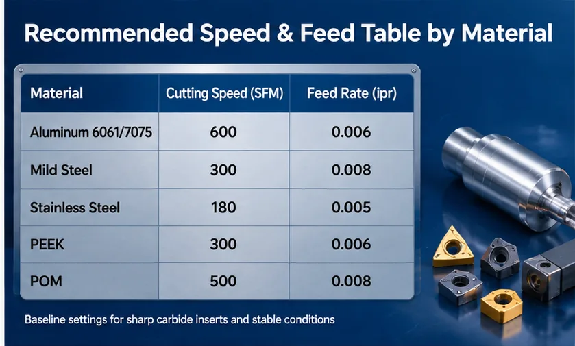
The table below lists practical baseline settings for conventional CNC turning with sharp carbide inserts, rigid fixturing, and stable cutting conditions. These are reference values for general turning, not guaranteed optimal settings for every tool grade, machine, or part geometry.
表格
| Material | Cutting Speed (SFM) | Feed Rate (ipr) |
|---|---|---|
| Aluminum 6061/7075 | 600 | 0.006 |
| Mild Steel | 300 | 0.008 |
| Stainless Steel | 180 | 0.005 |
| PEEK | 300 | 0.006 |
| POM | 500 | 0.008 |
This table assumes standard turning inserts. It does not include cutting depth, tool nose radius, coolant strategy, or exact tool coating grade; these must be set separately.
- Aluminum 6061 and 7075: High speed compatible with sharp carbide tools. Watch for built-up edge, chip evacuation issues and surface finish. Reduce parameters for thin walls or long slender parts.
- Mild steel: Moderate speed and controlled feed work for low-carbon steel. Tool grade, hardness and coolant delivery heavily influence usable limits.
- Stainless steel: Generates high heat and prone to work hardening. Adjust based on grade (304 / 316) and tool geometry. Maintain consistent cuts to avoid rubbing.
- PEEK: High-performance thermoplastic. Control heat buildup, clamping pressure and dimensional drift. Reinforced PEEK grades require modified settings.
- POM (Acetal): Preferred for stable precision plastic components. Use sharp tools, clean chip removal and controlled temperature to hold tolerances.
For extra engineering reference, consult https://www.engineeringtoolbox.com/ for machining guidelines and https://www.matweb.com/ for material datasheets. Always verify the exact alloy or polymer grade instead of relying only on generic material names.
Factors That Change Cutting Parameters
Baseline SFM and ipr values must be adjusted to match material, tooling, part geometry and production goals. A setting that works for a short rigid aluminum part often fails on a thin-walled stainless sleeve.
- Workpiece material and hardness Harder materials require lower cutting speeds or wear-resistant tool grades. Stainless steel, hardened steel and nickel alloys create high heat and fast tool wear. Soft materials can run faster but risk built-up edge and uncontrolled long chips. Material condition matters too: heat treatment, cold working, casting quality and batch variation change machinability.
- Cutting tool material and geometry Carbide inserts support higher speeds than HSS tools. Coatings, chipbreakers, rake angle, edge prep and nose radius change tool life and cutting force. Sharp positive-rake tools suit aluminum and plastics. Tougher carbide grades and dedicated chipbreakers are better for steel and interrupted cuts.
- Depth of cut Depth of cut is the radial material removed per turning pass. Deeper cuts increase cutting force and power draw. Excessive depth causes chatter, insert fracture, workpiece deflection and dimensional error. Roughing prioritizes fast material removal; finishing uses a light pass to hit diameter and surface finish targets.
- Workpiece diameter and spindle speed At fixed RPM, cutting speed rises with workpiece diameter. Smaller diameters need higher RPM to maintain target SFM. Constant surface speed (CSS) mode helps stabilize cutting speed as diameter changes, subject to machine maximum RPM and workholding limits.
- Part rigidity and workholding Long shafts, thin-walled tubes and high length-to-diameter ratio parts deflect and vibrate easily. Reduce cutting force, lower feed, shorten tool overhang, or use tailstock / steady rest. Thin parts deform under heavy chuck pressure. Clamp firmly enough to hold the blank without squeezing geometry out of tolerance.
- Coolant and lubrication Coolant reduces heat, improves chip flow and stabilizes cutting conditions. Options include flood coolant, MQL (minimum quantity lubrication), or dry cutting. For plastics, check coolant compatibility and thermal expansion; temperature shifts directly change final dimensions.
- Surface finish and dimensional tolerance Lower feed rate generally improves surface finish, but results also depend on tool nose radius, machine rigidity, vibration and tool wear.
Approximate theoretical Ra for turning: Ra ≈ f² / (32 × r) Ra and nose radius r use identical units; f = feed per revolution. This formula assumes a perfect circular nose and ignores vibration, material tearing, built-up edge and tool wear.
Tight tolerances usually need a dedicated finishing pass, tool wear compensation and thermal stabilization before inspection.
- Production volume and cycle time Prototype machining prioritizes validation and flexibility. Batch production balances cycle time, tool life, process capability and inspection frequency. Faster feeds or higher SFM cut cycle time, but extra tool wear and scrap risk may erase efficiency gains.
Common Turning Tooling Options

CNC turning uses specialized tools for OD turning, finishing, threading and forming. Tool selection depends on material, feature size, tolerance and clearance.
External turning tools Reduce outer diameter and machine cylindrical profiles for shafts, stepped diameters, tapers and shoulders. Tool geometry must provide clearance and avoid collision with adjacent features.
Facing tools Machine the end face of the rotating blank to create a flat, perpendicular reference surface. Facing sets part length and prepares faces for secondary operations.
Boring bars Enlarge or finish internal holes. Rigidity is critical for deep or small bores. Long overhang creates vibration and poor dimensional consistency.
Grooving and parting tools Grooving tools cut reliefs and snap-ring grooves. Parting tools separate finished parts from bar stock. Both work in tight cutting zones, so chip evacuation and alignment are critical.
Threading tools Single-point threading inserts or forming taps generate internal and external threads. Thread quality depends on profile, pitch, tool geometry and cutting strategy. Verify against ISO metric or UN thread standards.
Drilling tools Center drills, spot drills and deep-hole drills make axial holes on the lathe. Select based on hole size, depth, material and position tolerance.
Driven / live tools Turning centers with live tooling add cross-drilling, flats and slots without re-fixturing the part. This reduces handling and improves positional accuracy between turned and milled features.
When selecting tooling, check insert compatibility, holder clearance, overhang length, chip control and machine power limits.
CNC Turning vs Milling
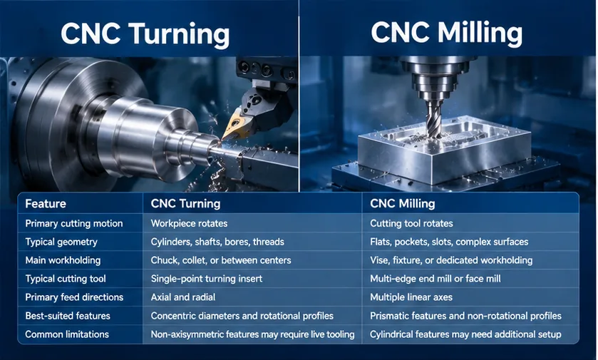
CNC turning and CNC milling are both subtractive CNC processes, but their core motion differs. Turning spins the workpiece while the tool feeds; milling spins the cutting tool while the workpiece moves.
表格
| Feature | CNC Turning | CNC Milling |
|---|---|---|
| Primary motion | Workpiece rotates | Cutting tool rotates |
| Typical geometry | Cylinders, shafts, bores, threads | Flats, pockets, slots, complex contours |
| Workholding | Chuck, collet, between centers | Vise, custom fixture |
| Cutting tool style | Single-point turning insert | End mill / face mill |
| Feed axes | Axial + radial | Multiple linear axes |
| Best for | Concentric, rotationally symmetric parts | Non-axisymmetric prismatic parts |
| Limitations | Non-round features need live tooling | Round features often need separate setup |
Choose CNC turning when main features share a central axis: pins, rollers, shafts, bushings and threaded fittings. One setup can machine multiple diameters and shoulders efficiently. Choose CNC milling for parts dominated by pockets, slots, irregular profiles and non-concentric features. Parts mixing rotational and prismatic geometry can use live-tool turning centers for single-setup work, or separate turning + milling operations for higher complexity. Process selection considers geometry, tolerance stack-up, surface finish, fixturing, order quantity and total cost. Single-setup workflows reduce alignment errors but are not always the cheapest option.
FAQ
What is the best cutting speed for CNC turning aluminum? For carbide turning of 6061 / 7075 aluminum, 600 SFM is a solid starting value. Final speed changes with insert geometry, machine stiffness, surface finish target and workpiece rigidity.
What feed rate should be used for CNC turning steel? 0.008 ipr works as a starting feed for general mild steel roughing. Finishing passes often run lower feed, while rigid roughing setups can support higher rates. Follow insert manufacturer data for final tuning.
How do I convert cutting speed from SFM to RPM? For diameter in inches: N = (12 × V) / (π × D). RPM equals SFM divided by the workpiece circumference (feet).
Does a higher feed rate always reduce machining time? Higher feed shortens pass time for fixed travel and RPM. Too much feed raises cutting force, ruins surface finish, accelerates wear and creates dimensional errors.
Can CNC turning machine engineering plastics such as PEEK and POM? Yes. CNC turning is widely used for PEEK and POM precision components. Use sharp edges, control heat, design proper clamping and account for thermal expansion. Filled/reinforced polymer grades require adjusted tooling and parameters.
What is the difference between rough turning and finish turning? Rough turning removes bulk material quickly and leaves a small stock allowance. Finish turning removes the remaining material to hit final dimensions, tolerances and surface roughness requirements.
How can chatter be reduced during CNC turning? Reduce tool overhang, improve clamping and setup rigidity, select suitable insert geometry, or adjust spindle speed and feed. Long thin parts may need tailstock, steady rest or lighter cuts.
How do I choose between CNC turning and CNC milling? Pick turning when key features are cylindrical or concentric. Pick milling for pockets, slots, flats and complex non-round shapes. Mixed parts can combine both operations on a live-tool lathe or separate machines.
Custom prototype and low-volume CNC parts can be produced using turning, milling, or a combination of both processes to match the part geometry and engineering requirements.


