
Updated on October 29, 2026
Sheet metal fabrication bends, cuts and assembles thin metal sheets into enclosures, brackets and housings. Common processes include laser cutting, bending, riveting, welding and powder coating. This guide covers bend allowance, minimum bend radius, hole-to-edge rules, tolerance and DFM tips for custom sheet metal prototype and low-volume orders.
Definition
Sheet metal fabrication is a subtractive and forming manufacturing process that transforms flat metal sheets into functional parts via cutting, bending, forming, joining and surface finishing. It is widely used to make enclosures, chassis, panels, brackets and structural housings for industrial equipment.
Common materials include aluminum, stainless steel, carbon steel and galvanized steel. Material selection is determined by strength, weight, corrosion resistance, conductivity and working environment.
Different from CNC machining which carves parts out of solid billets, sheet metal fabrication reshapes flat stock with minimal material removal. It is ideal for thin-walled, large-surface and lightweight structures.
For mechanical engineers, product designers and procurement buyers, sheet metal fabrication is flexible for sheet metal prototypes, low-volume custom parts and batch production. Custom designs can be adjusted to fit unique mounting structures and space constraints.
How It Works
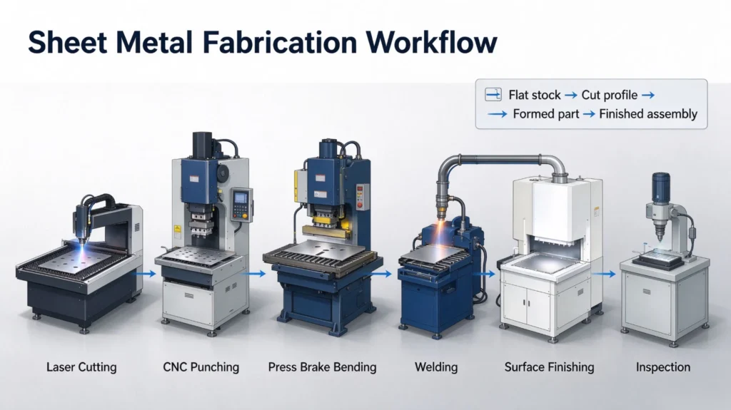
The workflow varies based on part geometry, material and order volume:
- CAD Design: Create 3D models and 2D drawings, generate flat patterns with bend allowance calculated
- Cutting: Laser cutting, CNC punching or shearing to separate profiles from raw sheets
- Bending & Forming: Press brakes form flanges, channels and 3D shapes; tool path planning avoids collision and deformation
- Joining: Welding, riveting, clinching or fastener assembly for multi-piece structures
- Finishing & Inspection: Deburr, anodize, powder coat or passivate; inspect dimensions, fit and surface quality
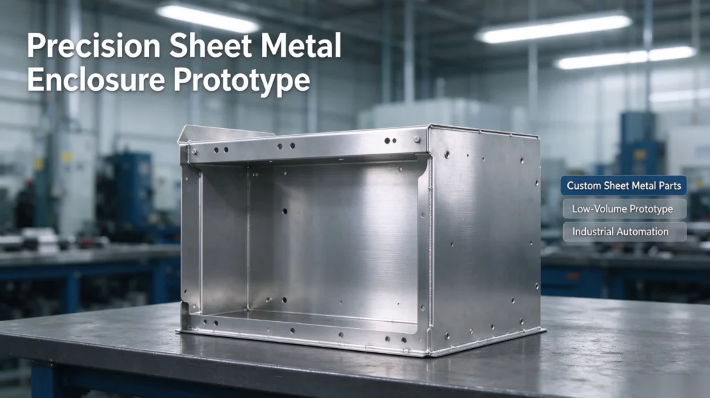
A sheet metal prototype helps test clearance and assembly performance before mass production investment.
Key Parameters
Core factors affecting manufacturability, quality and cost: material grade & gauge, minimum bend radius, springback & bend allowance, GD&T tolerances, surface finish, and production quantity (prototype / low volume).
表格
| Process | Best Suited For | Main Advantages | Key Considerations |
|---|---|---|---|
| Laser cutting | Complex contours, precision cutouts | High flexibility, no dedicated hard tooling | Heat-affected edge, material-dependent precision |
| CNC punching | Standard holes, repeated cutouts | Fast and cost-effective for repetitive features | Geometry limited by punch tool library |
| Press brake bending | Flanges, brackets, simple channels | Low tooling cost, flexible forming | Springback, minimum flange & radius limits |
| Welding | Permanent multi-part assembly | Strong structural joints | Heat distortion, post-weld correction needed |
| Powder coating | Protective & cosmetic finish | Uniform, durable corrosion resistance | Coating thickness changes fit and grounding |
Pros & Cons
✅ Advantages
- High material utilization, less waste than solid stock machining
- Strong design freedom for cutouts, bends and custom cut profiles
- Scalable: one-off prototype, small batch and repeat production
- Lightweight yet rigid structural performance
- Wide material options for corrosion, weight and strength needs
❌ Limitations
- Complex deep-formed shapes need extra tooling
- Thin and long parts are prone to bending tolerance drift
- Springback and weld distortion impact final dimension
- Not suitable for high-precision dense mechanical parts; CNC machining may be better
The best choice depends on part shape, tolerance, finish requirement and order quantity.
Typical Applications
- Aerospace: Non-flight critical panels, access covers, mounting brackets and equipment enclosures
- Medical equipment: Instrument chassis, cabinet housings, support brackets with clean-grade finishes
- Industrial automation: Machine guards, electrical enclosures, control panels and sensor mounting covers
- E-bike & mobility: Battery housings, controller boxes, protective brackets and lightweight accessories
We deliver precision sheet metal prototypes and low-volume custom sheet metal parts for these industries.
Design & Machining Tips
- Assign tight tolerances only on critical mating and alignment surfaces
- Follow minimum bend radius rules matching material thickness
- Keep holes and slots away from bend lines to prevent distortion
- Share K-factor / bend deduction data with your fabricator for accurate flat patterns
- Reserve space for fastener access and assembly operations
- Mark masking zones, grounding points and cosmetic areas on drawings for finishing
- Submit STEP files + 2D drawings for DFM review before quotation
Early DFM feedback reduces bend complexity, cuts cost and avoids costly design revisions.
FAQ
Q: What is the minimum bend radius for sheet metal?
A: The rule of thumb: minimum inside bend radius equals material thickness for steel and aluminum.

Q: How far should holes stay from a bend line?
A: Hole edges must be at least 1.5× material thickness away from bend lines to prevent distortion during bending.

Q: Sheet metal vs CNC machined housing?
A: Sheet metal is cheaper for large thin enclosures. CNC machining suits small, thick, high-precision structural housings.

Q: Can sheet metal parts achieve tight tolerances?
A: Bending introduces springback. Typical sheet metal tolerance is ±0.2–0.3 mm, less precise than CNC milling.


